Networking Multiple Vehicles: A Guide

Hello! My name is Sam Honor; I’m a first-year PhD student at WPI’s Automata Lab researching graph-neural-network control of marine robotic swarms.

Over the summer, I got a bunch of BlueRobotics hardware to set up. Now that the season is winding down, I’m paying my “documentation debt” with a few forum posts others may find useful. First in this series: setting up a multi-robot system with BlueROV2s and BlueBoats.

Posts I will probably do:

  • ROS 2 with multiple vehicles

  • So you want to use a Cerulean ROV locator deepside

  • Building a low-cost slip ring spool

  • Full stack simulation (real BlueOS containers + SITL autopilots on VMs) of multiple vehicles

    • NMEA protocol simulation of a ROV locator

I’m going to split this post into comments, as the editor is being awful when I try to paste stuff in.

I’d love to hear any questions or suggestions; there is probably some stuff in here that is suboptimal.

5 Likes

Step 0: Figure out how scalable everything needs to be.

Out of the box, BlueRobotics vehicles are designed to make it easy to connect a vehicle to a computer without much setup. Unfortunately, this takes up lots of USB ports (2 per vehicle if each has a controller), and can create a networking bottleneck if you’re using your laptop to route lots of data between vehicles. Using static IPs, USB ethernet, and mDNS will probably be fine if you’re using two, maybe three vehicles.

If you don’t want to make a whole setup with a router (as described in the rest of the post), here are the bare minimum steps you need to take to ensure that n > 1 vehicles plugged into USB ports on your computer behave nicely:

Make sure your vehicles and interfaces all have different IP addresses. The network setup tutorial instructs you to set a static IP address of 192.168.2.1 for your laptop USB ethernet port. Your vehicle has a default static IP of 192.168.2.2. Having different devices with the same IP will cause problems. In my initial setup of a multi robot system with static IPs, I just incremented the third octet by 1 for each vehicle. Note that you can change your vehicle’s static IP by clicking on the “network” icon next to the bell.

Make sure your vehicles have different MAVLink IDs. If you have multiple vehicles claiming to be “vehicle i”, MAVLink routing might get a bit screwy. Change the MAVLink ID of each vehicle by going into “Autopilot Parameters” and changing “SYSID_THISMAV” to something unique for every vehicle.

Change the mDNS address by clicking on the “pencil” button that appears when you hover over your vehicle’s name. Not sure this is strictly necessary if you just want to access your vehicles via IP, but it’s one of those “nice to have” changes.

Change MAVLink Endpoints. Your vehicle’s default topside endpoint is 192.168.2.1. If this is not the address of the interface your vehicle will be plugged into, you should change it.

With these bare minimum steps complete, you should be able to connect to each of your vehicles using Cockpit / QGC and control them ONE AT A TIME. For simultaneous control, see section 4.

1 Like

Step 1: Modify your BlueRobotics networking hardware

If you want to build a heavy-duty multi-robot system that includes a router, you’ll need to modify your FXTI boxes and BlueBoat base station. By default, both of these devices offer only USB ethernet ports. These are not compatible with routers.

Step 1.1: Ethernet-ify your FXTI box

The FathomX Tether Interface (FXTI) box is the blue box you plug the topside of your ROV tether into. From the factory, it offers only a USB-B port that handles both power and data. Fortunately, this just gets plugged into a USB-ethernet converter, and there’s a little ethernet cable that plugs into the actual guts.

Step 1.1.1: Manufacture a new back panel (or blow a hole in the original)

We want to run an ethernet cable through the back of the FXTI box and into the ethernet jack on the tether interface board. If you have access to a laser cutter or waterjet, you can:

  1. Download the CAD of the FXTI box

  2. Make a sketch out of the rear plate’s geometry, and draw a circle a little bit larger than the diameter of your ethernet cable (or a little bit larger than the diameter of a RJ45 jack if you’re using something pre-terminated) somewhere on the upper right

  3. Save the sketch as your preferred vector format, and cut

If it’s easier for you to drill through metal than to laser cut, just unscrew the back plate, pick a spot somewhere in the top right, and drill away.

Step 1.1.2: Terminate your cable and plug it in

Pass some unterminated ethernet cable through your hole, and terminate it on both ends (or just shove a terminated cable through if that’s what you went for). Then, plug the cable into the FXTI board and close it up.

In this configuration, the USB cable is used for power only. In the future, I may even add some sort of POE setup to eliminate the need for the USB altogether.

Step 1.2: Ethernet-ify your BlueBoat Base Station

This one is a little less “surgical”. I just tore the guts out, drilled a big (0.75 inch) hole in the right (opposite of antenna) side, and passed the ethernet cable through. Admittedly, this is not “splash proof”. I added an inline coupler on the outside so that I can move the BaseStation around more freely.

A better approach might have been to drill a small hole, pass some unterminated cable through, and terminate on both sides (and add an inline coupler to connect the new cable to the injection cable that goes into the router).

Step 2: Router software setup

In this setup, the router has three jobs:

  1. Run a DHCP server

  2. Run a DNS server (technically optional, but how many IPs are you willing to remember?)

  3. Route packets (duh)

Every router is different, but most modern ones can do these three things out of the box. If your router can’t run a DNS server in the factory configuration (like my Linksys wrt160n from 2007), there is almost certainly open-source firmware (I use DW-WRT) that can.

A very, very brief networking primer

If you aren’t a networking person, here’s what you need to know to understand what jobs the router does in this setup, and maybe have a starting point if you need to debug something.

  • DHCP (Dynamic Host Configuration Protocol) is a way of assigning IP addresses dynamically (i.e. not statically). When a client (like your vehicle or laptop) connects to a network, the DHCP server gives it an IP.

    • If your laptop or your vehicle isn’t getting an IP address, DHCP is probably configured wrong.

    • This could mean the DHCP server isn’t running (correctly) on the router, or that your vehicle isn’t configured to be a DHCP client.

  • A DNS Server (Domain Name System Server) handles translating between domain names (like “google.com”) and IP addresses (“142.251.167.138”). The DNS server in our system is only responsible for translating the addresses of our vehicles.

    • If you can ping your vehicle by its IP, but not its name, DNS is probably borked.

    • You can debug DNS issues with tools like “nslookup” (simple) “dig” (a bit complex, but more powerful)

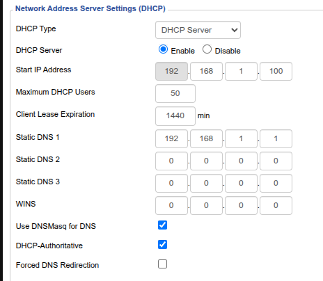
Step 2.1: Setup DHCP

Login to your router configuration page, and ensure that “DHCP Type” is DHCP server and/or that “DHCP Server” is “enabled”. Chances are, you won’t need to change anything.

Step 2.1.1: Make your vehicles DHCP clients

Go into the network menu, choose the ethernet interface, and select “dynamic IP”. Note: do not select the DHCP server option, as this will create a server to compete with the one on the router. This can bring your network to a halt.

Step 2.1.2: Make your BaseStation(s) a DHCP client(s)

By default, your BaseStation is an access point with a static IP address. Log in to the BaseStation web interface, and change “address acquisition” from “Static” to “Automatic”. Since the BaseStation is an access point, it will happily pass DHCP messages to and from your boats without any extra configuration.

Step 2.1.3: (optional; recommended) Create static DHCP reservations

Optionally (and I recommend this), you can also give your vehicles DHCP reservations. This means that each vehicle will get the same IP every time it joins the network. While this may sound like “static IPs with extra steps”, it gives you the advantage of being able to configure each one from a central location if you ever want to reallocate. Additionally, you can add new devices to the network, and they will get dynamic addresses without any special configuration.

In DDWRT, this requires adding the MAC address of the vehicle along with the IP you desire for it (make sure it’s in the range of your DHCP server; usually 192.168.1.101-151 by default)

Step 2.2: Setup DNS

If your router has friendly firmware, setting up DNS should be as easy as adding a hostname next to a static reservation. I recommend using the “.lan” TLD. If you use a TLD that is used for websites, you might not be able to connect to your vehicles while also connected to the internet, as the DNS server your ISP provides will handle that request and return an “idk who that is”.

NOTE: modern browsers might try to google “.lan”, as “.lan” is not a TLD that is used on the internet. To circumvent this, type “.lan**/**”. This will make the browser ask that address for a webpage.

To actually be able to access the DNS server (eg ping a domain) from a client, you’ll need to set the “static DNS server” on the router to be the router’s IP.

Step 3: Setup MAVLink IDs and Endpoints

Annoyingly, this is the part of the whole multi-robot setup where you need to do lots of repetitive configuration on all your systems. First, set your MAVLink IDs as discussed above. That’s the easy part.

The ugly part is configuring endpoints. (From what I understand) PyMavlink and MAVROS require that each vehicle gets its own socket on the host machine. For the PyMAVLink-based GCS discussed below, every vehicle must have a MAVLink client endpoint at a different port on the host. I say start at 15000 and increment by 1 for each vehicle.

The uglier part occurs if you want to have multiple processes talking to multiple vehicles. In that case you have two options:

  1. Put a MAVLink router on your computer that translates between vehicle input sockets and multiple shore-computer process sockets

  2. Put multiple shore-computer endpoints on each vehicle.

I was lazy and went with the second, though the first is probably a neater solution. If anyone knows a better way of doing this I’m all ears.

1 Like

Step 4 (the elephant in the room): Ground Control Software

Bad news: Cockpit and QGC do not support simultaneous control of multiple vehicles from a single computer. Good news: I wrote a lil script that does the bare minimum (arm/disarm, mode change, and control). Feel free to use and modify to your heart’s content.

If you value setting paths for your robot to follow, you should still be able to do that with Cockpit or QGC. Just open an instance on the vehicle you want to set a course for, plot and upload the course, and put the vehicle into AUTO mode when ready.

If you need to see a stream from your ROVs’ cameras, VLC works best–though it is finicky. I found that it doesn’t play nice with UDP video streams (VLC only works with UDP streams w/ MTU <= 1316; iirc Camera Manager was pushing out ~1400 byte packets according to my Wiresharking), so I recommend using RTSP streams. ADDITIONALLY, THE APT-INSTALL VERSION OF VLC IS INCOMPATIBLE WITH RTSP STREAMS!! I tend to prefer apt packages, though at the time of writing the snap install (or build from source) is the only one that will work.

To set your video stream to RTSP, go into “Video Streams”, then click the “pencil” button next to your ROV’s camera stream and change the protocol from UDP to RTSP. The URL will auto-populate.

To watch a RTSP stream using VLC, hit “ctrl-n” to open the “network stream” dialog, then copy the URL from the ROV’s “steam endpoint” field. Click on show more options, and make caching as low as you can put it without dropping too many frames. This will reduce latency.

I could see multiple cockpit instances also working for this.

If you want to see all your robots on a map, I recommend the Vizanti ROS 2 node. Setting ROS up, however, is a topic for another post.

1 Like