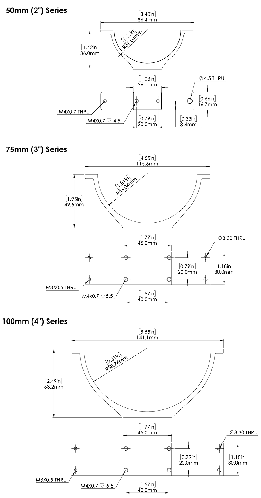
I have been looking at the mechanical drawings for the enclosure clamp, specifically the 3" series WTE3-M-CLAMP-R1, and comparing to the STEP file. Below they are overlaid:
I’m not great at CAD, but it appears that the center of the inner circle is 1 mm above the top of the left and right protrusions (for lack of a better name). The mechanical drawing doesn’t show this.
Can the team please confirm if this is accurate? Was this offset intentional? I’m trying to reproduce the clamp as a parametric model.
Hi @rgov -
Welcome to the forums! Happy to help with your question - I verified my own suspicion with the Design Engineer, and they confirmed the 1mm gap is intentional. This ensures the clamp always clamps! Great find.
Thanks @tony-white. A few more questions if you don’t mind:
The mechanical drawings for the 3" and 4" series show the M4 holes on the base being only 5.5 mm deep. In the CAD model the depth is 7.50 mm. Is there any clarification on this? Is it only threaded 5.5 mm?
Do you know the thickness of the “adhesive rubber strip” with the 2" model? The other sizes use 1.59 mm (1/16") strips for acrylic and 3.18 mm (1/8") for aluminum.
The specific product or vendor of the tape you use would be really helpful. For example McMaster-Carr sells rolls of adhesive neoprene strips in varying hardness ratings. 3M also has vinyl tape. Both are slightly too narrow.
I was restricted from posting links to the above products, which are:
 McMaster-Carr:
 1/16" x 1" - https://www.mcmaster.com/1376N13/
 1/8"  x 1" - https://www.mcmaster.com/1376N15/

 3M:
 1/16" x 1" - https://www.3m.com/3M/en_US/p/dc/v000089204/
 1/8"  x 1" - https://www.3m.com/3M/en_US/p/dc/v101409191/
I have a parametric model mostly done, needs some fillets and screw holes. And, of course, to be tested on a real enclosure.

