I believe you’re totally in the same boat as me. I use the T500’s with the BasicESC200’s but I think either the interference comes from the high power current, or either from the T500 themselves in combination with the PWM signals.
I tried out the QMC5883L in an external enclosure. This seemed to be an improvement, but it still didn’t give me the rock solid stability I was hoping for. I’m currently experimenting with setting up a MTi NMEA Heading sensor. The integration within BlueOS went pretty smooth, but I now only need to figure out how to make sure that the Heading Sensor is seen as the primairy (and maybe also the only) yaw source in the compass system.
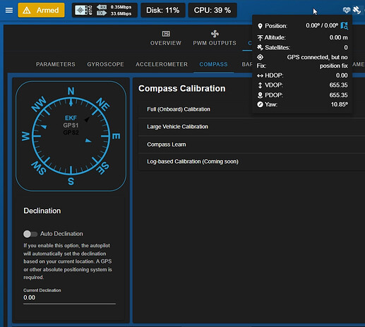
@tony-white any thoughts on this? I set up the Heading NMEA sensor as a GPS on Serial 3, with the NMEA protocol. GPS1 source in the compass tab is showing up correctly and being really nice and stable, but the actual EKF doesn’t really seem to do anything with the GPS1 Heading . I guess it’s due to a wrong EKF(3?) parameter setting?
A question, I have the IMU away from the battery and the ESCs and everything is fine, but I want to add a second battery about 15 cm from the IMU position. The ESCs will remain far away, but although I have to do tests, I would like to know your opinion. Will the battery create magnetic interference for the IMU compass?
Hey @tony-white , I’m still trying to figure things out to have the GPS Heading as our main heading source.
In the meantime, I discovered the COMPASS_ENABLE parameter in ArduSub, which made sure that the other compasses weren’t being used at all.
Now, I’m looking to set it up so that the GPS Yaw Heading is either the priority or at least still part of the EKF, but as the first compass. Right now, it seems like the GPS Yaw Heading isn’t really participating in the EKF at all. It also can’t be dragged in the priority list, since it’s not appearing in the priority list. (It is visible and working though in the little compass visualizer)
Any ideas on what I could tweak to get this working?
Hi @sietse -
Below find python script and instructions that sends both GPS and heading information to the autopilot as NMEA messages. If you’re sending the same NMEA heading messages correctly, and have setup the autopilot to receive them correctly, then you should be all set! I would guess checking the parameters in step 5 should get your setup working…
The setup:
In BlueOS, navigate to terminal, take red-pill, and nano a new file named fake_gps_yaw.py, save (cntrl o) and exit (cntrl x).
chmod +X fake_gps_yaw.py
Edit the file (nano fake_gps_yaw.py) and on line 96, change the IP address of the vehicle to an interface it has a connection on - typically this would be 192.168.2.2 as this is the static IP on the Pi ethernet adapter by default, the example is what I used for my unit that is only connected via WiFi and received that dhcp address.
response = requests.post(‘http://192.168.1.23:6040/mavlink’, json=payload)
Optionally edit the error message on line 101 to use the same IP address.
In autopilot parameters, verify that EK3_SRC1_POSXY, EK3_SRC1_YVELXY, EK3_SRC1_YAW, are all set to GPS. Also verify that GPS_TYPE is set to MAV.
Run the script. The vehicle will jump to the coordinates and heading described in the file, and update as the script runs - see the attached video. fake_gps_yaw.py.zip (3.2 KB)
I was wondering if there is an easier way of getting rid of the EKF for compasses and just have a way where the Heading GPS is just ‘wired’ straight to be used as the compass for the ROV.
SO for example if you only want to use the MTi as a NMEA Heading Sensor Input as a full replacement of the other compasses. So basically for the yaw / heading, only the NMEA Data gets used instead of some sort of blend between the GPS, MMC5883 and AK09915. Would taht be possible? To get rid of the onboard compasses fully and only use the NMEA Heading?
Hi @sietse -
The EKF is a requirement, but you can certainly disable the other compass sources so that only the external source is used. Simply disable those other sources at the bottom of the compass configuration page under Vehicle Setup!
I attached a video where it’s visible that I disabled the use for both compasses, so only The NMEA Heading Sensor (GPS2) should participate in the Compass System.
As you can see the final Cockpit compass angle (EKF Angle), doesn’t fully match the GPS2 Angle. It seems to be off by 10(?) degrees. I also tried to set the COMPASS_ENABLE parameter to 0. This leads to the AK and MMC compass not showing up in the BlueOS Compass at all. But still, the EKF Angle doesn’t seem to fully allign with the GPS2 Angle.
As I understand it the EKF also uses the gyroscope in its determination of attitude angles, to allow smoother, higher frequency updates than just those from the absolute orientation sensors (like a magnetometer and/or GPS setup for yaw, and an accelerometer for pitch/roll).
An EKF is a state estimator that tries to make practical sense of the measurements it’s receiving, factoring in uncertainty and changes over time. New samples contribute to its output, but it may not fully match measurements quickly (or ever) if it considers its state predictions to be within its estimate of the sensor error/inconsistency, or if the measurements are changing sporadically.
So it’s not possible to fully (and only) use the NMEA Heading angle as the one and only input for the ROV’s Compass? I experience an offset between the final EKF and the absolut GPS2 NMEA Heading Data, which would mean that the use of 1 absolute heading source will always have an offset compared to the final heading angle shown in QGC or Cockpit (Because of the EKF System)?
The reason we’d like to use a external heading source is because we’d like to navigate as precisely as possible on the A50 DVL. I believe the ROV Position Estimate that’s ‘drawn’ in QGC and Cockpit is based on the EKF’s angles and the DVL’s velocities and then get calculated in the actual positions, right? So in order to get an as precisely as possible position estimate, we need a super precise Compass Angle all the time, right? For our system the internal compasses experienced too much distortion from the Electromagnetic fields, so we choose for an external NMEA Heading Sensor, with slightly more precise and a higher range of operating in terms of mGauss.
Another point of relevance - the offset you’re seeing may simply be a visualisation of the compass declination, which is typically determined by the world magnetic model built into the autopilot.
How and where this is represented isn’t well documented at the moment, so hopefully @williangalvani can confirm whether the EKF represents orientations relative to true north (versus potentially magnetic north for your external heading source). You could also temporarily turn off autodeclination to see whether this is the source of the discrepancy.
I’m unsure, although it is at least possible to deprioritise the gyroscope values by increasing its specified noise rate in the EKF, which may be worth trying.
The autopilot estimates its position by blending the sensor values and inputs it has access to / is configured to use. The visual odometry API that’s used by the Water Linked DVL BlueOS Extension provides translational velocities, which are then blended with other sensors in the autopilot’s EKF to form position estimates via dead reckoning, relative to the initial position specified in the Extension (or updated occasionally using a GPS module or similar).
The DVL is also capable of performing its own dead reckoning estimates, using its internal sensors, but that is not how it is currently integrated with BlueOS, and it’s unclear whether that would improve performance or just make the integration more complicated.
Dead reckoning integrates rate measurements into position estimates, so any errors in those rates get included in the integration, and any bias in the error becomes an integrated bias in the position (i.e. there is a drift between the actual and estimated positions, which increases over time).
Minimising that drift requires accurate, high frequency sensor values, with minimal latency, but there are often tradeoffs between those factors that make them difficult to achieve with any given sensor, so it can be beneficial to combine the strengths of different sensor types.
As an example, even with perfectly accurate velocity and compass measurements, the latency to communicate them to the autopilot and (more significantly) the time in between those measurements both contribute to uncertainty in the position. That can be somewhat mitigated by having high frequency inertial measurements in that time (e.g. from an accelerometer and/or gyroscope), but they have their own associated inaccuracies and imprecision, so there’s no perfect solution. That said, some information (even if somewhat noisy) in the time between more accurate and less derivative measurements from other sources is typically more accurate than just assuming linear or step changes.
Was this due to the ESCs/motors (which can be compensated for), or from sources of electromagnetic noise in the environment (which would require a different type of sensor to avoid)?
Thanks you so much for the extensive reply! I appreciate it!
I tried this, and even after rebooting it didn’t really seem to make a difference.
So in theory, you’d like to have the EKF using the GPS heading aswell as the integrated compass data? Or would you rather go for GPS, but with integrated compass fallback?
I honestly didn’t think about this one! Really fair point!
Yes exactly! We’re using 4x T500 and 4x T200 Thrusters with custom batteries on 18V, limited to 90A total. We experience Compass drift when giving near full throttle. We experimented with the PSM, and had several ways of wiring the PSM. We tried out the Magfit Tool. This one measured 8000mGauss noise before using magfit and 1500mGauss after using magfit. In the meanwhile we did another revision on how we wire the PSM, so we hope to get even lower on the mGauss after using MagFit again.
The MTi would have served as a ful l replacement instead of usng the internal compasses. But Maybe we still need to use them like you said just to have some information in the time between.
My question is. If you’d just use and calibrate the two internal compasses, and you’d use the GPS2 aswell, how much is the GPS2 actually adding to the EKF?
That depends - if it’s less accurate and slower than a compass then it’s not worth adding, but if it’s similarly or more accurate (and potentially subject to different sources of error) then including both in the EKF could make sense if parameters allow it.
Fallback is another option, and also makes sense to enable if possible - the magnetic fields may be misleading, but a compass is typically less likely to lose signal than a GPS module (because the compass itself would need to fail, instead of just losing communication).
You can also use electromagnetic shielding if it’s relevant (which can be as simple as wrapping problematic wires/components in foil, albeit with some corresponding risks around accidentally contacting and shorting out other components/conductors).
“Need” is a strong word, but if you have a couple of different options in mind it can be worth trying to test them to determine which gives you the most accurate results.
An integration test (like station-keeping or path following) can be a decent way of comparing setups that may be difficult to reason about theoretically (especially given the complexities of some real world environments and noise sources).
In the ArduPilot case specifically I’m not sure, and I don’t currently have time to try to determine that from the code. There is some documentation available, but it’s not precise about contributions like this (although from what I understand only one of each sensor type is considered per lane, so it would likely only be using one compass at any given time - I’m uncertain whether/how it blends that with heading input from a GPS).
In general, an EKF is intended to use measurements and corresponding error estimates for each sensor to estimate states and corresponding uncertainties (factoring in growth over time), from which it can make predictions about the current state at any given point in time. How the measurement errors are determined depends on the implementation, but could be set manually via parameters (in which case the trust proportions can be directly tuned), or could be determined automatically using some kind of consistency/alignment metric (e.g. when there are multiple sources of similar data).
I already mentioned the user-definable noise rate of the gyroscope, but it’s possible GPS inputs instead base their noise on HDOP and accuracy values included in the GPS_INPUT MAVLink message
Hi @sietse
Your video is very interesting, you seem to have got the EKF to almost match the nmea compass,
Question, is this the exact unit you have? How do you make it ethernet connected?
Just to point out to anybody who hasn’t watched it, the black arrow (barely visible) is the GPS2 (nmea heading sensor), the light blue arrow is the EKF heading estimation.
Your NMEA heading sensor seems to be sending data at about 2Hz, and your EKF is being updated by your gyro at a much faster rate.
There is some discussion about the accuracy of the heading sensor not giving enough accuracy because it doesn’t poll quickly enough, so suggestion is to use the other sensors as a fallback.
But what you have there seems a lot better than what I usually see when operating the ROV (see below gif) and the idea of a slower or slightly delayed heading reading negatively affecting the EKF heading, I think is outweighed by how poorly my built in magnetometers are currently performing.
The ROV wasn’t moving at all when I took this, it was in the water with the thrusters on, but holding station.
I get the exact same behaviour on both of my ROVs, one uses 8x ESC500s and an aluminium enclosure (considering switching to acrylic to see if that improves things). The other is a blueROV with an acrylic enclosure.
I’m also considering putting an external ardupilot mag somewhere near the camera (further from the ESCs).
Since my last post about this
I’ve tried calibrating the magnetometers in BlueOS but it generally errors out at the end and I don’t think the values get saved. It’s quite an effort to calibrate (has to be done at home on my own), so I haven’t tried too many times. When I do I calibrate using QGC. I’ve always ensured to set up a GPS feed so the ROV knows it’s origin position.
Thank you so much for the extensive explanation @EliotBR!
This is a good one! We’ll test out some different setups. The Method with the path following could be a great way for us to compare the options.
Hey @XYZEng! We’re currently experimenting with a 600series MTi. We have it working over serial connection. It gives us NMEA, but over a serial connection!
To be honest, it’s has been some sort of bug during that session. After restarting the ROV, the GPS2 updated its values as fast as the other sensors. The MTi is set to give output at 10Hz. But yeah you got a fair point for the polling!
You got some interesting behaviour going on in that GIF! The T500’s / ESC’s really seem to have a lot of influence on the built in sensors. As Eliot mentioned, this could be handled by using Ardupilot’s MAGFIT Tool. Our plan is to rebuild our ROV at the moment, keep all the power cables as short as possible, get the right gauges, and perform a MAGFIT calibration / correction.
Please let me know what this does for you. I’m really curious on how the alluminum tube could affect those things!
I think this was only really properly configured since the ArduSub 4.5.3 / BlueOS 1.4.2 Update, so maybe in the meanwhile they got it working?
Last time I tried to configure an external QMC5883L to be just outside the electronics tube in a different enclosure. The calibration had to be done within QGC to get it all fully working.