Hey guys, so I am pretty new to using Blue Robotics products and was wondering how I would connect 6 T200 thrusters to a raspberry pi 4 for my ROV project. I want some confirmation that I can do this and some guidance on how to do it before I buy the materials. Can anyone offer some guidance?
Hi @kingcoolance -
Welcome to the forums!
The best way to connect those thrusters is with a Navigator, attached to your Pi. This will let you run BlueOS, and be off and running with your ROV in no time! If you’re trying to save a few bucks, an older pixhawk model may also work but you’ll lose the ability to run LUA scripts…
There is a vastly more complex approach where you would connect the 6 T200’s motor controller ESCs directly to GPIO output pins, but this doesn’t provide you with a motion sensor in the vehicle, and would not be supported by any of the software / firmware necessary… Not a recommended approach by any means!
1 Like
Thank you very much Tony, for responding. I will check in with my team about using a Navigator, and I will reach out if I need any assistance!
I was wondering if we could also connect servos (standard 270 or 180) to the navigator board. I see a lot of pins on the navigator, but I was wondering if we could build code supporting the servos. Additionally, If we are not using the blue robotics HD camera, what type of cameras can we use that fit with the navigator ports?
Hi @kingcoolance -
Yes, by default the Navigator GPIO pins are intended to output servo-style PWM signals - read more here.
As for cameras, BlueOS supports any USB camera with H264 compression, or any IP camera with RTSP / Onvif / H264 support (on the same network as the Raspberry Pi of course.)
1 Like
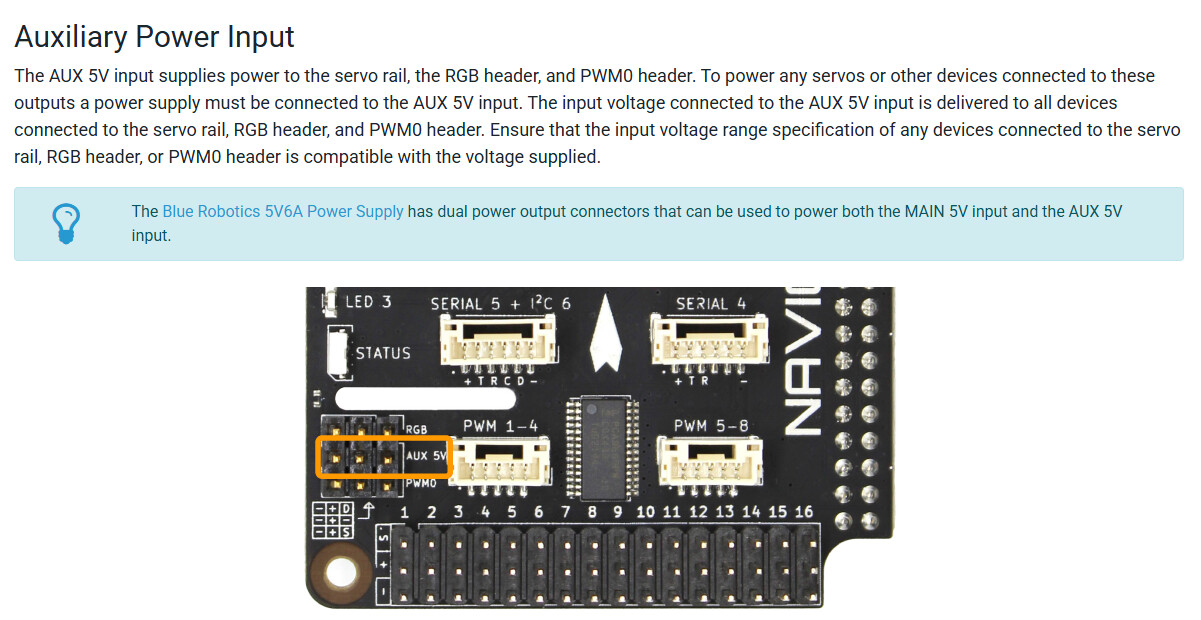
Hey Tony, I was wondering where the 12 V input comes in if the 6 thrusters are connected to the navigator board. Is it through the navigator or a separate supply from the tether? It is quite unclear to me. Also, the standard servos that require 12 V cannot be connected to the AUX inputs on the bottom of the navigation board because it only provides 5 V of power I believe? Can you please clarify my doubts? @tony-white
Hi @kingcoolance -
The thrusters don’t connect directly to the Navigator board! They connect to an ESC, a motor controller that sends 3 phase power to them. These ESCs are powered by a direct, high-current capacity connection. Thus, the connection for control signal that is made from the ESC to the Navigator is only a ground and 3.3V servo-style PWM signal.
As for powering a 12V servo, this can be done, but make sure no other low-voltage devices are connected as noted on the product page:
1 Like
So instead of using the BEC ( 5V6A Power supply), I should connect 12 V to the AUX 5V and only 5V to the main port?
Hi @kingcoolance -
If you’re trying to run a 12V servo, and are not using the RGB or PWM0 header, then yes, connecting 12V to Aux5V, and the 5V BEC to the main Navigator power power will get things running for both the Pi power supply and your high voltage servo.
1 Like
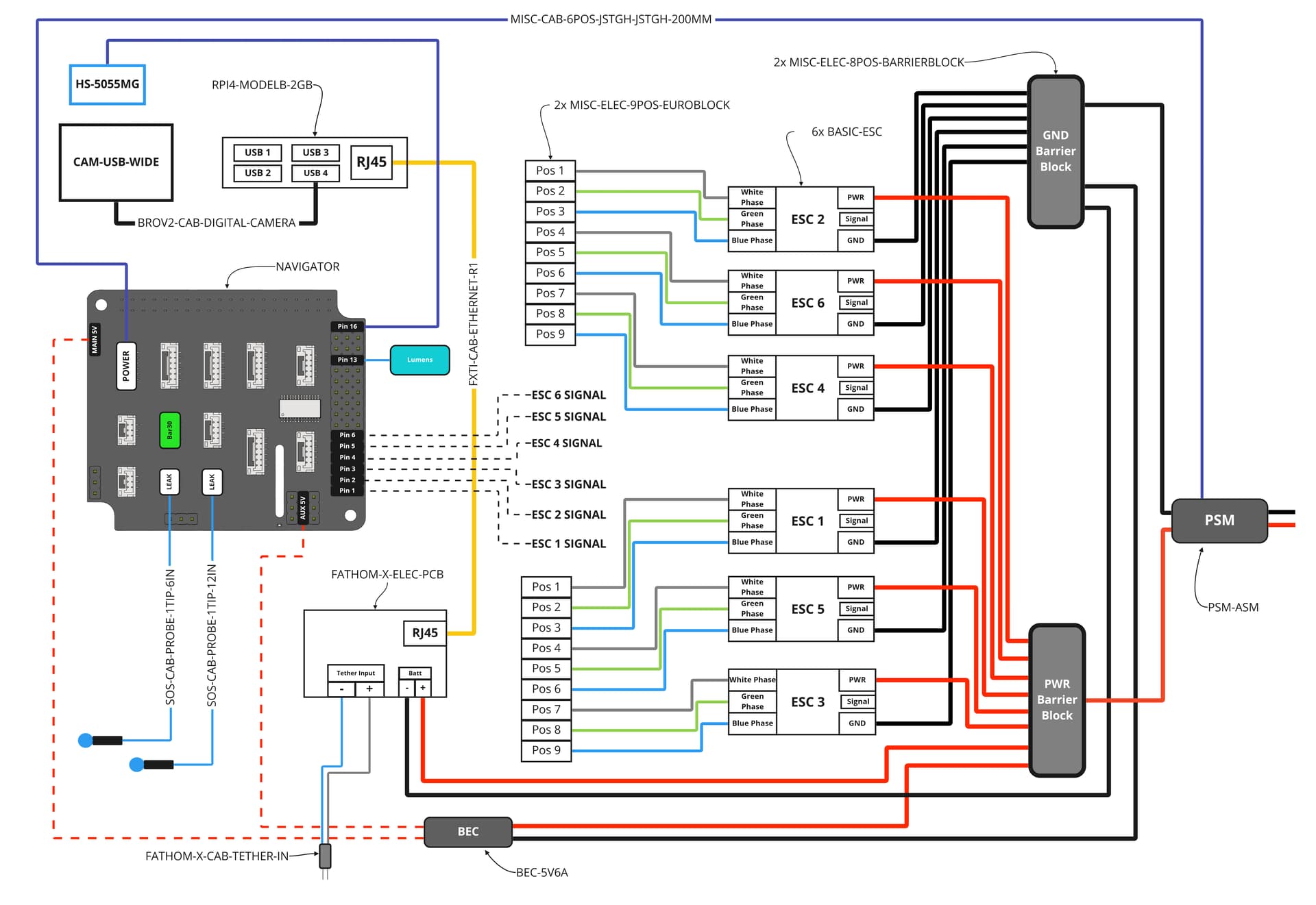
In this image (Blue ROV2 electrical diagram), it shows the 6 ESC signal wires connected to the first 6 rows of the AUX rail. If I was powering a 7.5V servo by putting 7.5 V into the AUX port, would it still be possible to connect these signal wires the first 6 rows as shown in this diagram? If not, where would I connect the ESC signal wires to?
Yes, the signal bus is driven by a PWM driver chip on the Navigator, and is unrelated to the voltage on the power rail.
It’s common for servo motors to be powered with a different voltage than their control signal, so this is how servo rails are designed to be set up. The AUX port is just a convenient external access to that power rail, which avoids needing to use up an output slot if your power supply is external (rather than being a BEC built into an ESC, for example).
1 Like