Modular Blue Robotics Based AUV

Context

For a while I have been dwelling about a simple AUV for assistance in several projects I am involved in. I have used a couple of commercial units and they have been successful but have had some (often significant) drawbacks which we (as a community) may in part be able to be overcome.

There have been a few somewhat more cost-effective units out there Seaber Yuco, (starting at about US$65k) MIT Sea Scout (commercialised here?), NemoSens, EcoMapper Nano (in collaboration with Seaber), Oceanscan LAUV (rental approx. US$2.5k/day) before you get into the bigger (and more commercial) units (the actual number of these smaller units in the field units would be interesting maybe aside from Seaber the others would be a handful or two each?)

Additionally, several people on the forum seem to be developing or progressing in somewhat similar directions and sharing of concepts may be advantageous to all.

Given that, my base core requirements are:

  • Must (Non-Negotiable for my use case) be able to be travel with it on international flights
    • Battery - Must be removable (not on several of the commercial units)
    • Battery - Must be able to be broken down into sub 100Whr elements (see here)
    • Weight - Unit without battery but plus hard travel case (say 10kg) must be less than 30kg (flight luggage limits)
  • Must able to scan medium sized areas (say 5km by 5km) can be across multiple missions
  • Ideally not be a 1 trick pony – able to be configured to give more than a single use case

Suggested Base Modular Blue Robotics Based AUV

The aim (in part) is to keep it using as many stock standard parts and systems as possible (to accelerate its use). But also, able to have modules swapped out as elements of the system develop. I see it all as a way to get something moving so some of the larger issues can be worked out sort of down the path similar to the initial Bluerobotics ROV.

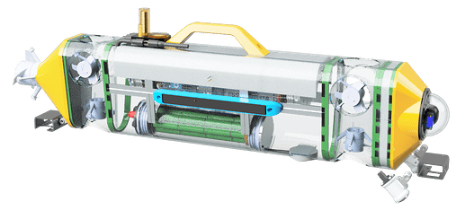
As it currently stands, I envisage the following style modules

  • Rear Thruster Module (about 1.6kg)
  • Lateral Thruster Module. (about 1.1kg)
  • Main Body Module (about 8.4kg with battery 6.9kg without)
    • Support Frame
    • Main 4” Electrics Enclosure with Integral Payload Electrics Tray
    • 3” Battery Enclosure
    • DVL add in module (nonbrand specific)
  • Nose Module (about 0.7kg with camera)
    • Camera / Lights Module
  • Handle / Communications Module (not detailed as yet)
  • Buoyancy Module
    • Nominal 60mm (0.9kg buoyant)
    • Nominal 100mm (1.6kg buoyant)
  • Ancillary Payload Module
    • Additional 4” Electrics Enclosure
    • Additional 3” Battery Enclosure

3D model Fusion Link https://a360.co/4lOpoXn

Medium unit with Side Scan and Camera module Unit Approximately 13.5kg (slightly buoyant as configured in the image)

Base Concept (11.6kg) with Pelican Air 1745 through to Most Module options (20.2kg) Side Scan Sonar, Additional thrusters, Ancillary Payload and Additional battery in a Pelican Air 1755

So, as I see it for a Base Unit

  • Blue Robotics Parts approximately Around US$5.5K (depth limit to 300-500 meters)
  • Batteries Around US$0.5K
  • Custom Pieces Around US$2K (I have access to 4 axis CNC, CNC Router and 3D printer)
  • DVL Brand and Feature dependent US$2K-10K (depth limit to say 300 meters)

Adding a Sidescan Module (fits within the proposed standard Main 4” Electrics Enclosure with Integral Payload Electrics Tray [takes up approx. ½ of Integral Payload Electrics Tray])

  • Sidescan Brand and Feature dependent US$2K-10K (depth limit to say 300 meters)

So, around the US$10K minimum (even less if no DVL and dragging a surface buoy for positional info) but more realistically a well-functioning unit around US$ 16.5K and with a few more tweaks US$26K broken up as. (to give indication as to where the most cost-effective cuts/tweaks can be made – [makes opensource underwater acoustics look good])

Source Minimum Well-functioning Higher end
Blue Robotics Parts 25% 24% 21%
DVL 20% 34% 30%
SSS 33% 31% 39%
Customs 16% 11% 10%

I have started to develop several (most of the modules above) to say a 50% design level (physicality sorted out but tweaking of where screw connections and alike still to be done). I believe strongly in the wisdom of the crowd and that this is not my design but open to all. Hence, I am looking for feedback, it’s easier and better to fix things on paper than when hardware has been purchased or fabricated.

I am not wedded to any specific concept and am happy to discuss any of the elements, there are some elements I have not started on (Handle / Communications module as I am in 2 thoughts (a fully integrated version [GPS and Lora in the main electronics and just aerials in the handle] or one which is a complete standalone unit [complete with independent battery and runs independent from the AUV/ROV]) Happy for peoples thoughts and concepts (I note @gunthix and his unit)

I see a large opportunity where a significant number of different payloads could be implemented to give really great versatility to this base backbone.

I will post more details of individual elements, I know I cannot do this alone (my software level is mmmmm average to poor on a good day basic)

Scott
4 Likes

Shortened Electronics Tray Module

Following on sharing

In brief this is just the standard Blue Robotics Electronic tray shortened up to allow for space to have a payload module within a standard 400mm 4” Enclosure.

It is being cut down from the standard unit and then mounted in a 400mm Aluminium Enclosure to give payloads tray of approximately 160 odd mm

For clarity the wiring harness (and their associated “holes” through the tray) have not been determined (often Red is indicated where I believe holes may be required)

3D model Fusion Link https://a360.co/4m0xPhS

This is anticipated to be achieved via the following modifications of a Standard Bluerov electronics tray

Standard Blue Robotics Electronics compared with the Proposed Shortened Electronics Tray Module

Removals

  • Removal of the Blue Robotics Camera and mounts (it is for an AUV) (Option to mount this camera in the Nose Module)
  • Removal of the Blue Robotics Fathom for the tender (it is for an AUV) (Option to mount this on the Payload Electronics Tray)

Modifications

  • Shorten the Hex Stand off from the Flange to the Tray from the standard 31mm to 26mm to give slightly more space on the shortened tray
  • Shorten the Standard Electronics Tray from 212mm to 160mm
  • Remove the Blue Robotics 8-Circuit Barrier Block (nominal 9.5mm spacing) and replace this with
  • Add a 12 Circuit Eurostyle Terminal Strip (6 +ve / 6 -ve)(nominal 8mm spacing 300V 20 A per connection) to act as power distribution (1 power in from Power Sense Module and 5 out to the ESC’s).
    • Note 1 the 2 outer terminals (1 each side) may need the top of the plastic trimmed to suit the 4” Housing curvature
    • Note 2 I understand and acknowledge the Blue Robotics ESC’s are rated at 30 Amp and these are rated at 20 Amp, but in this AUV configuration is not expected to use the motors at (approx.) above say 10A (likely 5-8A absolute max)
    • Note 3 The ESC cables will have the Fork/Spade lug removed and cable cut to length and routed through the Tray and to the ESC’s
  • Use Terminal Strip jumpers (Jumper Bar, 6 Pole, Black, 8 mm Spacing) (70A rating) Also see Note 2
  • Mount all ESC’s on the 1 side of the Tray (1 / 3 /5 Esc’s configuration dependent of AUV configuration)
  • Rotate all ESC’s 180 degrees so only 2 power (+ve/-ve) cables per ESC do a U turn rather than 3 phase cables per ESC
  • Base 3 ESC’s on the tray and have 2 on raised Teir (only required if 2nd lateral module is installed in the AUV)
  • Move the ESC 3 phase cables connection Euro Terminal back on the Electronics Tray to where the power terminal had been on that side of the board. Have the ESC 3 phase cables connected directly to Euro Terminal
    • Note 4 The ESC cables will have the motor phase cable cut to length
  • Approximately where Fathom had been mounted, mount the GPS Module (tentative may also be moved to the mast) and the LORA module (similar tentative). Mount an Ethernet switch above these 2 modules

Add a custom (3D print) Barrier Terminal onto the top of the Eurostyle Terminal Strip to provide 2 terminals (per polarity) to connect full battery voltage items (power supply to the - 5V power supply, ethernet switch, power to the payload tray, power to the camera/lights module)

Concept custom barrier terminal for battery power distribution

So, what am I after

Feeback, (BlueRobotics?)

  • Is this proposed layout feasible (I did look at the bend radius of the ESC’s cables I assumed 10AWG hence approx. 7mm bend radius and it appears to work)
  • Does it have some inherent issue (?RFI interference) (I have assumed I will put in access for the SD card for the PI) I am unsure how this may be affected by upgrading to Raspberry Pi 5

Things not worked out yet

  • The 5V DC cable routings
  • If something needs 3.3VDC
  • Support frames have not been fully modelled

Contemplating

I understand that a few of the commercial units have had issues with RFI, I have been toying with building the support frame from a laminate to lower RFI (say constructed to be a part Faraday cage from a laminate made up from epoxy glued sheets of 1mm plastic / 1.5mm Aluminium / 1mm plastic). Any thoughts, is this just over the top? or for a single custom build just another step?

Scott

3 Likes

Hi @Scott_W, thanks for sharing! :smiley:

Lots of interesting ideas here - hopefully others will jump in with relevant thoughts and insights. This could definitely be a valuable project for a lot of people.


Some comments/notes:

Your initial post had some broken formatting, so I’ve updated that to make it easier to parse and navigate.

This doesn’t seem to be loading correctly:

For custom setups I’d be more inclined to suggest our RAILS system, which has trays of various sizes and shapes, with more ways to attach things :slight_smile:

As a starting point, it may be sufficient to attach things to enclosures with some clamps. Building up from a stripped down base allows you to determine what is actually necessary, while also providing a platform to test subsystems and sub-assemblies as soon as possible to identify potential issues early on.

If it’s practical it seems worth starting out without advanced frame manufacturing and seeing whether the potential issue shows itself. Premature optimisation can take a lot of resources without necessarily solving the core problems of the project, so I’d be inclined to shelve this as a “maybe but hopefully not required” stage that can be investigated before fully committing to it.

Hi Eliot

Thanks for the response (and cleaning up my posting mess)

Firstly, I want people to challenge my ideas/concepts, if I can’t justify a design choice or direction then it is likely wrong so I expect to I have to explain these choices given that please don’t take anything the wrong way if I say I have looked at that

Sorry about that, hopefully this one will [a new link from the app but I do note the same address and I just get a spinning loading file] https://a360.co/4lOpoXn but I am starting to think it may be the size of the file (this top level file is made up of all of the sub components and it may be a little large? the electronics link in the 2nd post seems to workseems to work)

I had looked at the rails system at this stage I am chasing millimetres inside the housing so am still not sure which way to jump


I had started modelling using the clamps (this version is about rev 5 of the AUV) but the sides of the clamps put a fair amount more surface area into the profile (and so I moved away from them) and I would still need the ability to mount additional modules along the lateral line

Eliot more as a heads up I know that the Seaber Yuco did have issues with RFI in the sidescan data (I have heard it from 2 sources who worked on the project) and I know integrating payloads into Remus’s that this has been an issue

Again, if I can’t justify a design direction it likely should be changed and this is the sort of thing I hope people can challenge to optimise the unit

Scott

Of course - design is an iterative process, and I’m sure there are also various factors you’ve considered that aren’t yet fully captured in the goals you’ve presented here :slight_smile:

I’m not getting the error anymore, but it does seem to be spinning endlessly (or I’m just not waiting long enough for it to load). The second link works fine for me too :slight_smile:

Given the hole placement and mounting options of the RAILS system it seems difficult for the standard tray to compete, especially since you can readily have gaps between different RAILS modules, or design and 3D print your own to slot into the system as relevant.

If that’s a relevant concern then fair enough, although they may be sufficient to start with (while getting the rest of the system working), and it may also be possible to avoid a casing around the enclosures with the right design.

This could potentially be achieved with additional clamps, rotated so the flat sides face out. That said, I’m not sure how that would factor into weight and body smoothness considerations.

Interesting to know about, although before attempting to enclose the entire vehicle it seems worth trying to determine the source of that noise, and whether it is possible to avoid or isolate some other way. As an example if it’s caused by fluctuations in the power supply, travelling through the cable, then a casing could be irrelevant.

Worth noting that I’m not experienced in RF engineering - just trying to think about what’s involved here, and how it could express itself :slight_smile:

Battery Module

My most core design requirement is for the power system to be able to broken down (battery removed from the AUV and battery broken into sub 100Wh elements)

I considered a few different configurations but came back to standard 3” tube (in part as I have a couple of non air transportable batteries that I can use in the system on local projects).

After saying I need to be able to remove the battery for air transport, after much working out of very small boats (islander canoes) and having lost more electrical equipment to letting out the magic smoke in those boats, it is also important that components only need to be opened when needed (ideally not on the boats). Hence also looking at both a battery isolation system and a battery charging in situ answer.

I looked into a few threads but space for a SSR will be an issue and just breaking the power cables with a subconn style plug is not really on the cards given the amperage.

I fell into 2 thoughts either using 4 by 2S4P with integral BMS to allow charging without balance leads or using 4 by 8S battery’s run in both series and parallel in the Enclosure (series for AUV operation and parallel for charging)

Link to the Fusion 3D file Fusion

I feel that the 4 by 8S battery configuration will be an easier implementation although it will likely mean I will have to build up the batteries myself (I also have access to a battery welder) but has some limitations. (build would only be a couple of spacers to set the shape of the battery pack, a couple of Epoxy Insulation Board 0.5mm sheets, a couple of Nickel 0.2mm and some 100mm Heatshrink PVC and some 11AWG Silicone wire)

By running 4 batteries in 8S configuration full current draw is coming from each pack (ie 80-100 amp) so I should be using nominally XT90’s but this is especially tight. I have already a 70 amp limitation in the electronics Terminal Strip Jumper Bar so am looking at using XT60’s (I did look around at “short burst” over current). Under normal operation it should be a more consistent 5amps or less (peak around maybe 10 amp)

I thinking I am settling for 4 connections (+ve wire / -ve wire / PRV (or vent) / a 3 or 4 wire lead to a subconn plug or alike mounted external to the AUV)

I think using the Battery Switch Kit for BlueROV2 from UnderseaROV may be the way to go as it fits into the end cap (note Fieldwerx Mosfet system seem to have disappeared)

I see that I would not use a standard Bluerov switch inside the AUV skin but run a cable to the outside skin of the AUV, this cable would be (at least) +ve and -ve nominal 3.7V 4 by 8 Series (i.e. 32 series) for battery charging (say 10-20 Amp) and then a dummy plug set up to be a switch (plugged in turns on the unit). I am still tossing up if on the 3.7V or the 14.4V side [leaning to 4 wire 14.4V as its what’s standardly wired in the unit from UnderseaROV].

Endurance

Given this power (basically a 4S8P 18650 battery around 5200mAhr)

THIS IS ALL THEORETICAL and Not Correct (it is just used to give a guess of what the unit could do as a starting point)

Given Eliot’s data in this thread and working backward

For a given pumping flowrate of a thruster (sort of equal to speed of the AUV (Only if you ignore friction etc))

For a T200 @ 14V

m/s knots RPM PWM (µs) Current (A) Power (W) Force (Kg f) Efficiency (g/W) Endurance (hr) Endurance@66% (hr)
1.0 1.9 826.4 1571.0 0.2 2.8 0.3 90.0 69.3 46.2
1.5 2.9 1239.6 1608.0 0.8 11.2 0.6 51.4 17.3 11.5
2.0 3.9 1652.8 1655.0 2.0 28.0 1.0 36.4 6.9 4.6
2.5 4.9 2066.0 1707.0 4.2 58.8 1.6 27.6 3.3 2.2
3.0 5.8 2479.2 1762.0 7.6 106.4 2.4 22.5 1.8 1.2

For a T500 @ 14V

m/s knots RPM PWM (µs) Current (A) Power (W) Force (Kg f) Efficiency (g/W) Endurance (hr) Endurance@66% (hr)
1.0 1.9 439.9 1553.0 0.3 4.7 0.3 56.9 40.8 27.2
1.5 2.9 659.9 1588.0 0.9 13.2 0.7 56.3 14.8 9.8
2.0 3.9 879.9 1628.0 1.9 26.5 1.3 49.4 7.3 4.9
2.5 4.9 1099.9 1668.0 3.4 47.0 2.0 42.6 4.1 2.7
3.0 5.8 1319.8 1712.0 5.2 72.6 2.8 39.1 2.7 1.8

From this it can be seen there is an efficiency swap over between the T200 and the T500 at around say 1.7m/s (hence the decision for the T500)

Thus with the proposed battery (and the posabiltiy to add other battery modules as well) this gives scanning areas of approximatly X meters by X meters at the following speeds and lane spacing (eg a 2m/s and a 4m lane spacing you could do a 264m by 264m box area)

Speed m/s 1 1.5 2 2.5 3
Endurance @66% Hrs 27.2 9.8 4.9 2.7 1.8
Range km 97.8 35.4 17.5 9.9 6.4
Photogrammetry 8 884.5 531.9 374.1 281.4 226.4
4 625.4 376.1 264.6 198.9 160.1
2 442.2 266.0 187.1 140.7 113.2
Sidescan 150 3,830 2,303 1,620 1,218 980
60 2,422 1,457 1,025 771 620

I looked at 21700 batteries and the additional length was difficult, and 26650 work but would not fit back into the flange so overall length was also an issue, I also understand this is theoretical and does not account greatly for drag (other than derating the power to 2/3 of its capacity)

So where am I wrong and what do I need to fix what can be done better

2 Likes

HI @Scott_W,

I’m a fair way down my own “choose your own adventure” AUV story. I’ll share what I’ve done but I do not suggest it’s optimal. Mine is just one of many possibilities, based on trading relative capabilities.

I wanted an AUV that could spin in place and efficiently travel in the axis direction. I didn’t care about lateral movement at all, so I needed to minimise cross section. I was also absolutely against rotating shaft seals, which is why using the T200 thrusters was the starting point.

I’ve based things around three coaxial 4” x 300mm tubes. I designed a custom mechanical part that allows two end flanges to join face to face and also provide six penetrator sites. That part required a CNC with a rotary axis, so I had to job it out. With three tube sections, I have two coupler assemblies so there are 12 penetrators in all. Four are used for motors arranged kind of like an X-wing fighter, one is for depth sensor and one is pressure relief. The other 6 are nominally two side scans, a CT probe and external light and depth pinger, but these are all optional. The basic mass (without sidescan) is a bit under 12kg.

I have a dome at each end of the overall tube. One end holds a combination GPS and LoRa antenna, as well as recovery lights, and the other end holds a camera. In a perfect world the domes would be a more streamlined shape, but the domes at least let the antennas and camera protrude a little from the tubes.

From the get go, I’ve had a spreadsheet so that I could obsess about the weight budget. I think one of the real advantages of the aluminium tubes over the acrylic is that they compress less. So even if you’re not planning on going deeper than the acrylic would support, it’s worth using aluminium simply so that the buoyancy is more consistent. Ultimately I trying to get as close to net zero buoyancy as I can. If I can achieve this in fresh water, I can easily add mass when in salt.

I have a bunch of custom boards. One looks after the motors, battery balancing, orientation and depth. Another one looks after acoustic sensing, conductivity temperature sensor and talking to depth pinger. Another is a carrier for the radios and SD card storage. If I ever put sidescan and a camera in there, I’ll need to add a Rasp-Pi or something similar too, and some buoyancy foam because the mass budget will be out the window.

My batteries completely fail your limits. I have 4 sets of 4S4P x 18650 cells. Each of the four packs is 16x3.5Ah * 3.7V = 207Wh. It would be hard to break them into smaller units, but not impossible I suppose. The current arrangement has the cells in a hexagonal pack of 3,4,5,4, which just fits inside the 4” tube. I understand the airline’s reluctance to carry lithium batteries about, but there is a big difference between a flat foil pack type and my rigidly mounted cylindrical cells inside a mechanical pressure vessel. But rules is rules.

This is a lot of battery. It’s all brought together using XT60 plugs on two boards that are also the carriers for the ESCs, for 20A input fuses on the batteries and power FETs to completely power down the ESCs. The motors plug right into that board. A pair of XT60s on the other side are also the charge input along with the balancer plug. It plugs into a 30A charger I have left over from my quadcopter days.

You can see that my boards are stacked perpendicular to the long axis. This orientation works best for me.

1 Like

Hi @psupine

Great to hear another story about someone heading down this crazy path

So, correct me if I am wrong in how I interpret your unit your unit, it is (sort of) a long torpedo shape of 3 by 4” 300mm tubes connected together as basically a single chamber with 4 thrusters.

I understand the not needing lateral movement and broadly for scanning I TOTALLY get it (I’m also sort of hoping to use mine as a pseudo ROV as well (pluggable tether) as all of the DPAA Missions require one on site – PS I have also been thinking/looking at collision avoidance [WPNAV_TER_MARGIN] and given the 2 vertical thrusters this may assist in that quite a bit)

I haven’t posted my thoughts on the Sidescan as yet (I will in the next few days) Reading between the lines I suspect you are leaning towards a dual frequency (High / Low) unit. I’ve run a lot of towed dual frequency SSS units (maybe 3 or 4 different brands and a few different single frequency units) and they are great (they can scan a large area but are also able to detail a target, but, impossible to travel with on flights).

For the AUV I have been in discussions with most of the SSS suppliers (interested to hear your thoughts here) and I am leaning towards units where the electronics units are able to run multiple (but single) frequency transducers (ie scan a large area with a single low frequency transducer to get the needed swath to cover the search area, then on a separate mission unplug [subconn or alike] the LF transducers and swap to some HF Transducers [?900kHz?] and run a mission just over the targets from the earlier mission(s)) hopefully to save same $’s and space in the AUV at the cost of having to post process data each night (as I do currently anyway to set dive targets) to better document the targets.

I would also be interested in your LoRa (and its integration), I have been playing around with some higher-level functional description style docs as to what is needed from the existing Ardu / Blue OS software environment (still verbalising sort of fault conditions stuff eg Motors spinning and no movement → stuck or motors fouled do what?, Motors spinning with too great a current draw →dragging something do what?)

Great to hear of what you are doing

Scott

Hi Scott,

So, correct me if I am wrong in how I interpret your unit, it is (sort of) a long torpedo shape of 3 by 4” 300mm tubes connected together as basically a single chamber with 4 thrusters.

Yep, exactly that. With the domes and the couplers it is 1100mm, with the thrusters 1/3 of the way along (or 2/3 depending on what counts as forwards or up). This approach minimises the cross-section. I think the coefficient of drag for the domes is something like 0.4. I have some ideas for getting better streamlining, but none of those ideas are particularly good yet.

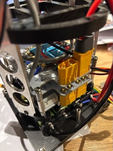
Mounting the thrusters like this is good for efficient flow, but it leaves them a bit exposed and liable to get damaged in handling. A carry handle could mount between the couplers. You can see a little lift point on the coupler that is in the background. The foreground red cap is over a relief valve.The BR change to include locking rings on the flanges made a fantastic difference to simplifying the external structure.

Getting the penetrators in exactly the right place on a such short cable is also tricky.

For the AUV I have been in discussions with most of the SSS suppliers (interested to hear your thoughts here) …

My primary focus is passive monitoring of whale calls at low frequency.

I haven’t thought a lot about the sidescan, but I’m certainly familiar with them and multi beam survey sonars. The sidescan capability might come later, and I think I’d be more interested in the HF end (more compact and at lower power) rather than pushing a greater survey rate of effort. There’s no lock in about that preference - it could change.

I would also be interested in your LoRa (and its integration) …

I’m using the WisBlock boards from RAK. They are basically an Arduino like environment with a radio software stack built in, and a bunch of peripheral sensors you can plug in. Naturally there are aspects that are frustrating, but on the whole they’re not bad. I’m only running LoRa peer-to-peer because I don’t expect there to be a nearby internet to talk to and it takes less traffic than running LoRaWAN.

Part of the integration problem is to lift the LoRa antenna above the water to clear chop and get a decent horizon. My approach is to put the antenna in on the end of the tube (the 2/3 end) and the thrusters hold around half the overall length vertically out of the water during radio comms. It’s not too bad because the relatively small body rides the swell, but I wouldn’t expect anything to work in bigger sea-states.

I don’t use any of the Ardu / Blue OS environment, which may or may not have been a mistake. I’ve certainly had to write an awful lot of code :face_with_bags_under_eyes:

My comms link looks like a bunch of waypoints in one direction and a bunch of “I’m located here and I heard such and such and this timestamp” in the other direction. Everything is squeezed to minimum length messages because LoRa is a shared space and the data rates are very low if you want to get decent range out of it. This approach is a good rehearsal for how things will be when direct to satellite IoT becomes ubiquitous, so it’s not a lost effort. I also use the BLE link for close comms at a higher rate.

I hope some of that helps.

Hi Scott,

I was just reading the IATA document you referenced.

It seems to me that shipping a package containing more than 100Wh of lithium batteries contained in equipment is OK on cargo plane for packages up to 35kg.

It’s getting on a passenger flight that you’re trying to achieve, right? It’s conceivable that a 12kg AUV could be split into three packages of batteries “packed with equipment”, each less than the 5kg limit. Having three equipment boxes under 5kg (plus another box with.the charger and tools). Each of my four battery packs, for example is about 1kg.

With this in mind, it’s not hard to have the sections plug together, before adding the outer tubes and running the vacuum test. Then you’re on the ground with a working AUV again.

That being said, I wouldn’t want to be the first person to try to explain to Qantas check-in that these are the rules. Good luck with that :slight_smile:

Hi @psupine

Yes, the main issue is the 100Wh limit (there is a case where it can be increased to 160Wh under some circumstances – I have managed to do this (160Wh) once with a good 10-minute discussion with the planes captain – I feel I only got it across the line as we had just found a downed aircraft and could show him an article in the local paper using the equipment)

Under the 100Wh is not too much of an issue declare it at the check in desk and then typically a chat to a supervisor and then all good

The overall weight is not as much of an issue if it’s under 23kg just normal check in (may be oversized) if between 23-30kg its just overweight and pay for the extra kgs

My last trip I think I had 110kg’s of equipment (Marine Magnetics Mag / Bluerobotics ROV / Dive Gear) over a few pelican cases (all individually under the 30kg limit) over 3 flights each way (International and then smaller and smaller local island hoppers)

It can be done through Cargo but at best it will just get you to an international hub (not the island hoppers) (can also be done via sea freight) and often the logistics (trying to find someone to send it too if you are not already in country) can be very interesting and it is not cheap

Try walking into the airport with a couple of the Pelican Gun Cases of hydrograpic gear :wink:

Scott

Main Payload Tray Module

The Payload fits at the other end of the 400mm Aluminium Enclosure from the Shortened Electronics Tray Module.

It is accessed from the other end from the Shortened Electronics Tray Module so all connections from the Electronics Tray Module to the Main Payload Tray Module are externally routed so that each end (Electronics Tray) can be removed

3D Fusion Model Fusion

The interconnection is envisaged as Bluerobotics Ethernet and Power Cable This cable has separate wires for Ethernet and power transmission, making it a useful cable for many different types of underwater connections! Ethernet is unshielded 26 AWG twisted pairs and the power is thicker 22 AWG to handle higher current applications

Thus, both Power (full battery voltage if 5VDC is required then an additional 5V 6A Power Supply would need to be installed) and Ethernet connection is available to the main payload tray.

It is envisaged that an additional Ethernet Switch would be fitted in this module (daisy chained to one in the main Shortened Electronics Tray Module). I am envisaging mounting a Fathom on my version of the AUV mounted here so I can connect a tether for development and running as a ROV.

This gives a fair amount of free space for additional payloads. I suspect there will be some sort of terminal strip and then space to add whatever payload modules people wish/develop and or a higher-level supervisory computer to provide additional computations.

Sidescan Payload Tray Module

3D Fusion Link Fusion

So, I have somewhat fixed views in what I am looking for in a sidescan. My ideal unit has something low frequency (say 100kHz - 200kHz -I currently use 100kHz for my primary large area searches) and then something on the High Frequency (say 800kHz – 1.2MHz) to document targets and sites. I am happy for this to be a swap over (ideally just the transducers) it does not have to be a full dual frequency unit.

So, I have approached a number of suppliers see below (I did not approach some of the bigger suppliers in the industry as I know their cost and physical size will likely be prohibitive – eg Klein, Edgetech). I am unsure of Kogger


Top Row - Cerulean / Deepvision

Middle Row ImageX / Marine Sonic

Bottom Row Blueprint Subsea on the payload module

I am happy for any of the supplier on the forum to chirp in about the pro’s and cons of their own specific units (Cerulean - @ljlukis) (Deepvision -@uffe) (I’m not sure but @paul-unterweiser may be tied up with Imagenex) (Michael Shekunov @KOGGER)

Cerulean

Omniscan 450 Side Scan Sonar around the US$5.5K – Advantages (Large advantage) already in the Bluerobotics environment, competitively priced, will fit on the standard Payload Module. Disadvantages single (450kHz) frequency transducer

Deepvision

Deepvision OEM Module around the US$7.3K – Advantages standard multi frequency PCB unit (200kHz/340kHz/680kHz plus custom) with single frequency transducers (inc in $’s additional transducers pairs around US$2.8K), will fit on the proposed standard Payload Module, has been integrated into at least 1 BlueROV. Disadvantages No specific Interface written as yet for BlueOS, a step up in cost.

ImageX

Imagenex Ethernet Sidescan Kit – around the US$6.5 – 8.0K Advantages standard multi frequency PCB unit (260 kHz / 330 kHz / 800 kHz nominal frequencies), with single frequency transducers, will (can be made to) fit on the proposed standard Payload Module. Disadvantages May need a little more squeezing to make it fit well on the Payload Module No specific Interface written as yet for BlueOS,

Marine Sonic

Sea Scan ARC Scout Mk II around the US$24K Advantages 150 kHz to 1800 kHz Options, will fit on the standard Payload Module. Disadvantages No specific Interface written as yet for BlueOS has been run in ROS the unit is controlled with either JSON or HTML messages through a user configured IP address through UDP in a packet format SDK available to be integrated

Blueprint Subsea

Starfish Module around the US$6.4K either 450kHz or 1MHz can’t be swapped Disadvantages No specific Interface written as yet for BlueOS and will only provide a SDK to write your own programming under a NDL (ie not opensource “from the looks of it, it is possible for to create and publish a BlueOS extension without breaking the NDA, but you would need to be very careful about not making any of the SDK (or equivalent code derived from it) public in source code form”), Does NOT fit on the standard Payload Module so would have to be housed in an additional Enclosure.

I see no matter the brand of the side scan there will need to be additional operations to make a decent usable result I would see the need for post processing (aside from standard Side scan processing)

  1. The ability to modify what the AUV recorded track (assumed EFK3 fusion) was of the AUV with a post dive correction (ie where did the unit come up and where the unit thought it came up, to where the GPS actually showed it came up) and integrate this with the XTF file in post process

  2. During the mission ability to start and stop the unit during different periods of the mission (stop on the end of a scan lane and start a new file)

Scott

I have seen crosstalk on SONARs. Main issue is switching power supply noise in the SONAR band. In and ideal world the whole AUV would be desinged to minimize noise from other components.

@Scott_W, thanks for sending me the link.

Very interesting thread. Used all my breaks today to finish it.

Happy to know other people are thinking about how to make this more practical and more accessible. I’m totally on board with a community driven design(s). My background is Electrical Engineering… worked designing PCB and digital processing in a sonar company (digital/power supply side) several years, have used IVER3 and REMUS100 vehicles in the past.

I can see how different requirements and personal experiences lead to different design choices. On my part, I’m going the traditional (torpedo looking) AUV style with fins… mostly because I need a vehicle that is stable and has low drag coefficient while going at 2-4 knots… but it won’t be stable at low speeds.

Regarding the batteries, I totally agree with you. I’m also interested in transporting this on a commercial airplane and bringing at least some batteries on the flight would be ideal. There is some risk that if batteries have different voltages, it could cause a fire. So, planning for a safe way to connect them would be important. I suppose a “smart BMS” could monitor all the voltages, charge the batteries, balance, shutdown in case of emergency, etc. To get me started I just built 4s2p x 4 (21700 5Ah cells) to provide ~850Wh.

Here is a list of items I think the community could be a part of:

  1. Acoustic modem. Mostly for feedback of status/location. Some open-source projects are out there but nothing completely ready to use. Last week I planned a design for a Raspberry Pi based acoustic modem… but I need to build it and figure out the driver’s situation. There is code for the Rpi to modulate and demodulate, including the doppler shift… so that could be used? Also went down the rabbit hole of how to properly design a transducer that can reach 2km. My hope is that all parts will cost < $400.

  2. Mast with sensors. GPS, WIFI, Iridium, LoRa, 4G/5G, etc??

  3. INS. iXBlue is ~$100kUSD with import duties to the US. There are other options like Advanced Navigation. Lower cost INS (MEMS based) start at $20USD but better ones I have seen are around $2000… but they don’t integrate the DVL or pressure sensor. Does the PX4 do this? Or someone could figure out a way to make a low-cost FOG INS :blush:

  4. Software. Perhaps BlueOS can handle all this but I’m not too familiar with it.

    1. I’m thinking ROS2 would be a great backend

    2. Configuration: adding waypoints, depth, enabling camera/SONAR, etc.

    3. Status of everything (INS calibration, vehicle position, battery, etc.)

  5. Module I/F. My hope is to make it modular and that different payloads can be added. Normally I have seen 2 things in AUVs. They have a cable mess like the REMUS 100 and Iver, which creates noise.

1 Like

Hi @bryan3D,

I used to design sonars too.

The DSP part is relatively cheap. In my experience, it’s the wet components that are the most expensive. If you can roll an effective transducer solution for $400, I’ll certainly use it.

I rolled my own. The usual bunch of 3D acceleration/gyro/mag MEMS didn’t have good enough specs for me. So I picked a high end accelerometer and mag sensor solution, ignored the gyro because I don’t think it is worth the energy cost in this application and made an INS. It also uses the bar1000 depth sensor, but no doppler log because that is too power hungry, heavy and expensive. I thought, how hard can an INS be? It turns out … surprisingly hard, but not impossible.

1 Like

The materials for the transducer shouldn’t be too expensive… but trial it will be a bit of trial and error. Aiming for TVR >142dB re 1uPa/V and RVR/OCR better than -190dB re 1V/uPa @ 24KHz or so just below resonance.

1 Like

Ah, cool. Yeah, I got a few cheap ones just to have as a baseline. Which sensors did you end up using? What performance do you get? There are some fancy TDK gyroscopes and accelerometers that are > $700USD per axis. Not sure I want to spend that much… but it beats $30kUSD for a low end navigation grade INS.

Which DVL are you talking about? The A50 is very small… unless your platform is a lot smaller.

1 Like

I’m currently using the Analog Devices ADXL355 and PNI RN3100. The accelerometer is on the same board as its host processor, but the mag sensor sits alone as far from the motor switching and battery packs as is feasible in a little AUV.

With calibration I get the bias to under 0.1deg, at which point I’m not setup to measure it further. The measurement noise is a function of how long you want to stare at the data. I think I was also getting something like 0.1deg at around 10Hz (but it’s been a while since I was working on it). I should also be clear that it’s not really an INS, just a good AHRS.

If you are unsure about paying for the fancy TDK gyros, imagine how I feel about the A50 DVL. It’s a nice little product, sure, but I don’t think I need it.

1 Like

Those are great numbers. The biggest issue I see with high end navigation INS is that they are manufactured for aerospace and military applications. We don’t have the G’s, speed, vibration, or temperature requirements hence a simpler, perhaps custom solution, should work at a much lower cost. My biggest concern is being able to detect drift from currents. Ideally I would like to be at <0.2% of distance traveled… realistically I would be happy with <0.5%. No more than 2km before surfacing… unless I was deep for some reason.

Typo: should be RM3100.

Certainly the whole ITARs restrictions make things harder, but it is what it is, and it’s there for a reason. You have to design up to that edge without stepping over it.

The lower noise requires solutions that consume much more power and that runs directly against the idea of designing for batteries. A proper INS, with FOGs and super sensitive accelerometers is beyond my budget in terms of money, mass and power. Instead I focussed on getting really accurate attitude control, which I can do while drawing way less than a milliamp and weighing a few grams.

I don’t think that I’ll get 0.5% of distance error on an uncorrected run, but for my application I don’t need to. I have a few ideas to help here, but none of them are really developed yet and I’m not yet up to that part of testing.