Looking awsome !!! Do you know the grip force in the claw? Would you be capable to insert a cutter for cutting ropes ?
No data on grip force yet. I have the info from the motors somewhere, but we are not 100% sure we have the right motors for the job (maybe 85%). For the time being, the motors are too strong for the internal gears (currently made from laser-cut acrylic for prototyping purposes), breaking them when used at full speed.
We have just got our CNC up and running, and our SLS printer is hopefully just around the corner too, so we’ll provide more feedback when we have the next iteration up and running.
But rope cutting should be fine. We have made some holes in the finger designs in order to be able to fit some blades
2 Likes
Hey Guys,
This is the gripper we are working on. This is actually a open/close gripper nothing else, designed for one of our clients. it will be possible to open 12cm as maximum.
The time to start printing these parts had started ![]()

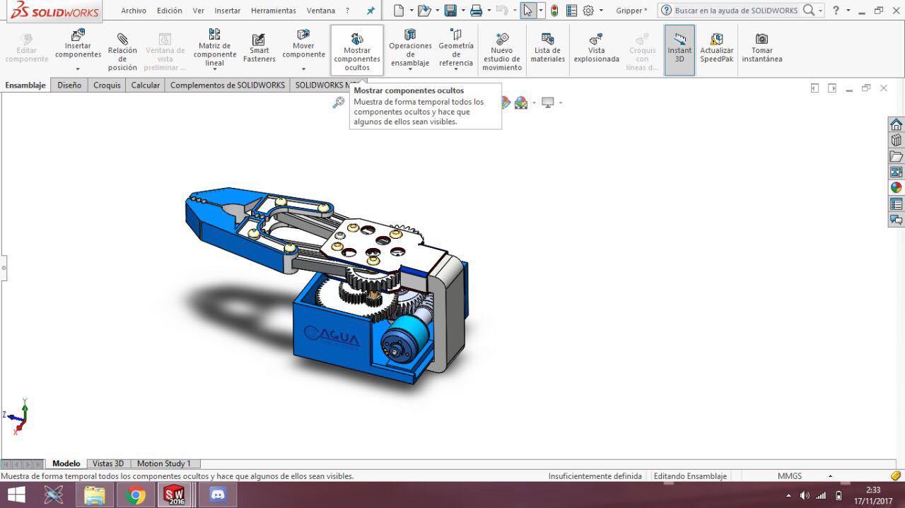
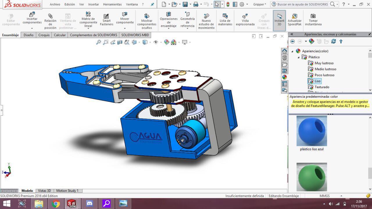
Any suggestions on which material to use after prototyping?
Regards,
Luis


@luisgamez How were you going to mount the M100 to a bulkhead? I agree that this is a good approach, I’d be a bit concerned about how much the M100 is going to wobble around like that.
Hey @kevink,
Lol I didn’t see we forgot to add the M100 mount to the bulkhead ![]()
![]()
I’ll keep you posted on the last design but believe me is going to be well mounted ![]() .
.
Regards,
Luis
I did some prototyping this past week with the parts from a “Makeblock” kit. There appear to be 2 primary design concepts as shown in the most recent posts above. One design is gearing on the gripper arms themselves where the other design is a center screw with a retracting bar. I am leaning towards the center screw design as I feel I will be better able to waterproof a single shaft, compared to 2 shafts. I also plan to use a stepper motor so I can set max open and max close positions based on the steps/rotation of the motor.
![IMG_2250[1]](https://us1.discourse-cdn.com/flex019/uploads/bluerobotics/original/2X/4/4cddd78ac031220167e1924bfc2fbf4abe2b8eea.JPG)
![IMG_2249[1]](https://us1.discourse-cdn.com/flex019/uploads/bluerobotics/original/2X/6/6f410da5e0967dbf04ce663a70dbb856ca4937fd.JPG)
I built the robotic arm shown below (along with my ROV control console).
Each section has a PIC and one or two motors. Control is by I2C on 2 wires plus +12v and gnd wires inside the tubing. The gripper pod has a camera, lights, lazer sizing, and it rotates. The other arm movements are obvious with left/right, arm up/down, wrist in/out and rotate. The video monitor shows the camera view.
A big challenge is to make the arm neutral buoyant otherwise it will tip the ROV when deployed. It folds and deploys to a start position with one instructon, then is controlled by two joysticks. It is basically working but requires some adjustments before adding it to my ROV.

3 Likes
Wow, Peter, that’s very impressive looking! I’d love to see a video of it operating if you have that.
Speechless!! Incredible !! As Rusty asks, do you have a video of the arm in operation? What wet weight of the manip as of now? Truly looks like a great piece of engineering.
I am working on a couple of issues so cannot film or weigh in water which is one of the issues. I know it is slightly heavier than neutral buoyancy.
If anyone has a 3-D printer and would like to collaborate I can send my drawings.
You MUST have a lathe/mill combo at minimum to build one of these. I now see a 3D printer can make many parts and simplify the construction.
The end-cap design solved many of my problems of making the sections waterproof while having easy access for maintenance. My original design took over an hour to take apart and re-assemble, the new design comes apart in 30 seconds and does not require any calibration to re-assemble in less than a minute.
I use dual shaft motors from Tsiny (Ebay) but they are heavy. I can increase buoyancy by making the tubes longer or wider but this makes them heavier and there is very little gained. There is a limit to the metal I can remove. The big issue is the motor weight and since I only need the dual shaft motor at the base, and only to lift the arm in air, the solution is to replace the other motors with lighter ones which I have not been able to find in dual shaft. My target is to have an arm robust enough to work in air so it does not self-destruct in testing. It does not have to lift anything heavy in water because the ROV will simply go the other way. The thrusters have limited ability to hold the ROV on the bottom. The solution to lifting, say an outboard motor, is to take a cable down from the surface and hook it on. My gripper is $20 from Ebay and there were two problems. It was designed for a servo drive which has numerous problems. I solved this with a right-angle gear driven by a gear-head motor making it smaller, easier to seal, and easy to add grip strength setting. The metal grips do not hold hard objects well and the solution is to slip surgical tubing over the ends.
My interest in 3D printing is to make a single shaft version end-cap to solve my buoyancy problem.
In my ROV I am also replacing the compass and pitch and roll clinometers with a single I2C module (working), replacing the wire-wrap boards with PCBs (made), and trying to get the Bar30 sensor software working (see my other post).
I am not sure if I have hi-jacked someone else’s thread with this post and apologize if I have. Posting on Forums is not my strong point. I hope my Bar30 post is on a new thread.
Peter.

3 Likes
…should get the cutting toll like Hydro-lec`s gripper… when arm open, the cutter is closed… and ive used on a Agus Rover mk 2 and its actually a Good solution…did a Lot of different work with that arm . and it Works…Allways good to have a cutter Anyway ![]()
What kind of sealing is used for the shafts?
1 Like
Hello Guys,
It´s been a while since we havent had any news about anybody designing their own grabbers, we at AQUA Exploración have done a lot of tests and prototypes trying to use the current BR T100´s and T200´s as servos but we have found it quite difficult, today browsing in the internet I´ve Found this:

as the description says: “First open and close testing of a magnetically coupled gripper for an ROV. Inside the PVC tube is a DC gearmotor, which is used as a linear actuator to translate a neodymium magnet. Embedded in the yellow ring on the outside are a number of other neodymium magnets. The linear coupling force of the magnets is approx 1.8kg.”
This seems a very nice approach for me, have anybody tried this? I´d like to give it a try with this magnets.
1 Like

Hallo Paul @PaulP,
nice manipulator … is it the Reach 5 mini model from the Blueprintlab?
How did you interface it to the BlueROV and how did you controll it?
Can you maybe send me the price you pay for it per pm?
Thanks
Hi Sven,
Yes it is. Controlled via seperate topside software and a script on the PI.
Shoot at email through to info@blueprintlab.com